Specification
|
Item
|
Unit
|
Specification
|
|
CATV Wavelength
|
nm
|
1550±10
|
|
Optical Input Power
|
dBm
|
-18~+2
|
|
Optical AGC Range
|
dBm
|
-11~+2
|
|
CATV Optical input port
|
|
SC/APC
|
|
RF connector
|
|
F-Female
|
|
Frequency
|
MHz
|
47~1000
|
|
Flatness
|
dB
|
≤±1.25
|
|
RF Output Level (in AGC range)
|
dBμV
|
≥80
|
|
Output RF resistance
|
Ω
|
75
|
|
Output Return Loss
|
dB
|
≤-12
|
|
C/N
|
dB
|
≥43
|
-9dBm Optical input power, 60 PAL channels
|
|
C/CSO
|
dB
|
≥55
|
|
C/CTB
|
dB
|
≥55
|
|
MER
|
dB
|
≥31
|
-15dBm optical input power
|
|
Power Supply Voltage
|
AC\V
|
100~240 (Input of adaptor)
|
|
Input Voltage
|
DC\V
|
+5V/12V(Input of product, output of adaptor)
|
|
Power Dissipation
|
W
|
≤2
|
|
Operating Temperature
|
℃
|
-10~+50
|
|
Dimension
|
mm
|
95×60×23 (L×W×H)
|
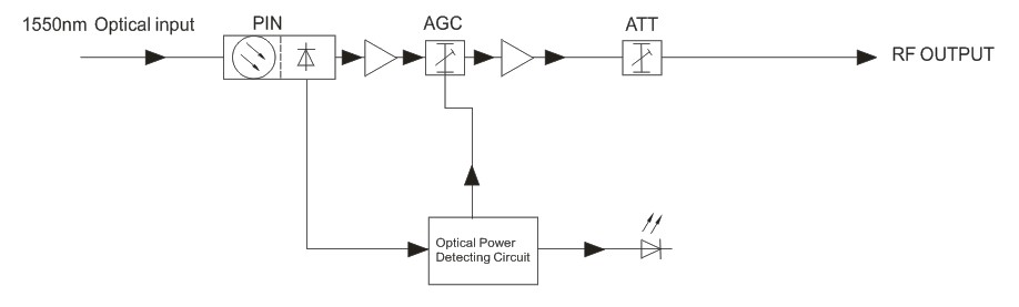
Block Diagram
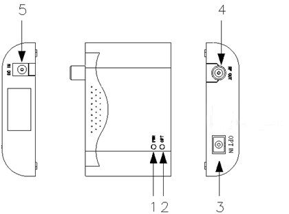
Interface introduction
1. LED indicator for power supply. If power supply works normally, the LED indicator will be green; if fails or power off, the indicator will be off.
2. LED indicator for optical receiving power. When optical receiving power is higher than -12dBm, the LED indicator will be green. When optical receiving power is lower than -12dBm, the LED indicator will be red.
3. CATV optical input port: SC/APC.
4. RF output port. Use coaxial cable to connect with the RF input port of TV or STB.
5. Power input port. Connect with the attached power adaptor.